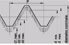
Threads: profiles and types
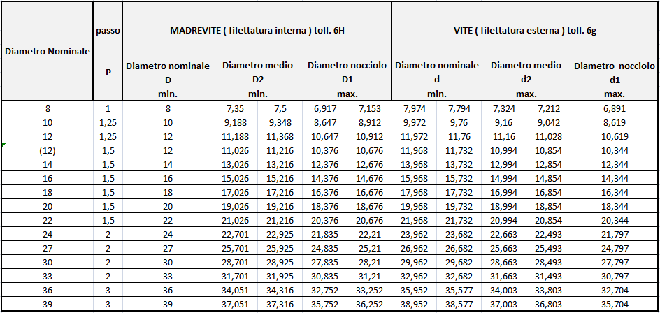
1.1 COARSE PITCH thread tolerance grade 6H / 6g


Effect of electroplating:
After coating, the dimensions of the screws may exceed the maximum limit, as long as they do not exceed the nominal dimensions allowed for position h.
After coating, the dimensions of nuts may be smaller than the minimum limit, as long as they remain within the nominal dimensions allowed for position H.
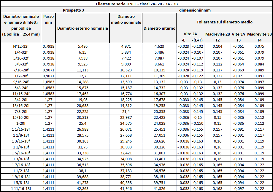
1.2 FINE PITCH thread tolerance grade 6H / 6g

Effect of electroplating:
After coating, the dimensions of the screws may exceed the maximum limit, as long as they do not exceed the nominal dimensions allowed for position h.
After coating, the dimensions of nuts may be smaller than the minimum limit, as long as they remain within the nominal dimensions allowed for position H.
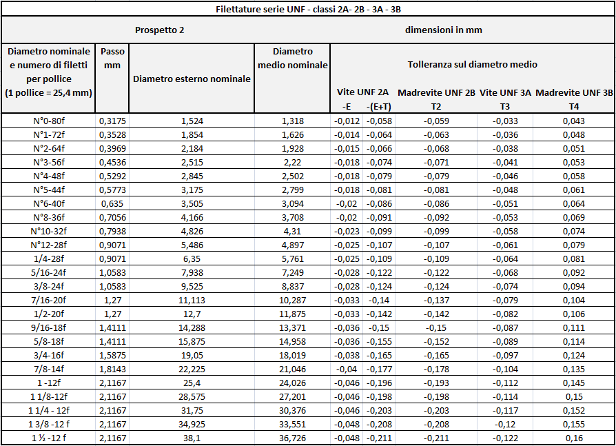
2. ASA THREADS – (extract ASA B1-1 / 1960)

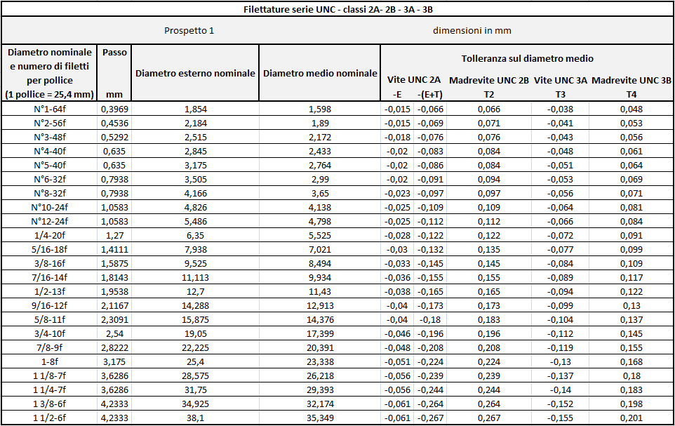
Meaning of the various symbols: As an example, we will analyze this thread designation:
3/8 - 16 UNC - 2A:
3/8 = Nominal Size (Thread Diameter)
16 = Pitch (16 threads per inch / 1 inch = 25.4 mm)
U = Unified Thread, normally adopted in all English-speaking countries
NC = Coarse pitch (NF = Fine pitch: NEF= Extra fine pitch)
2 = Degree of tolerance (in this case medium degree)
A = Means that the entire designation refers to the screw (B refers to the nut)
There are three degrees of tolerance:
- Coarse
- Medium
- Precise
3. NPT THREADS – American Standard Taper Pipe Thread (extract USAS B2-1 / 1968)


The bisector of the angle of the fillet is perpendicular to the axis of the cone.

Other American Pipe Threads :
NPTR (National Pipe Taper Railing Fittings) internal and external taper.
NPTF (National Pipe Taper Fuel and Oil) internal and external conical leak-proof.
NPSI (National Pipe Straight Intermediate) internal cylindrical, watertight.
NPSF (National Pipe Straight Fuel and Oil) internal cylindrical, watertight.
NPSC (National Pipe Straight Coupling) internal cylindrical.
NPSH (National Pipe Straight Hose Coupling) internal cylindrical.
NPSM (National Pipe Straight Mechanical) internal and external cylindrical.
NPSL (National Pipe Straight Locknut) internal and external cylindrical.
4. WHITWORTH THREADS – (UNI 2709 extract)
Threads in brackets should be used only when absolutely necessary. For the calculation procedure of the geometric elements of WithWorth threads, see UNI 2708.
5. PIPE THREADS
5.1 For NON-SEALING coupling on the thread (UNI ISO 228/1 extract)

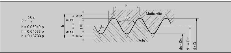
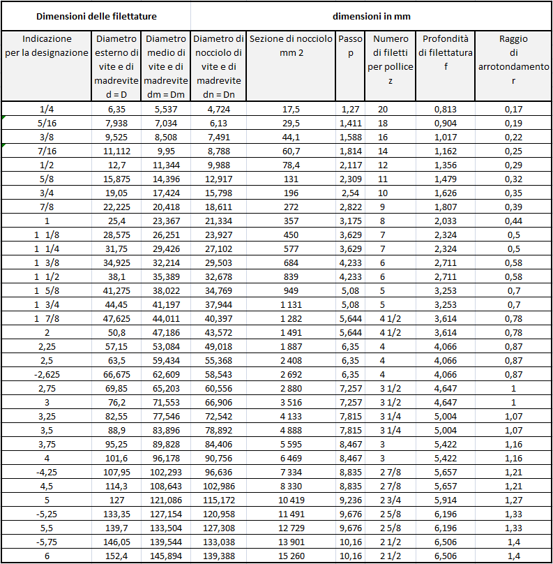
H = 0.960 491 P
h = 0.640 327 P
r = 0.137 329 P

1) For thin-walled parts, tolerances apply to the mean diameter determined as the arithmetic mean between two diameters measured perpendicularly.
6. PIPE THREADS
6.1 For THREAD-SEAL coupling (UNI ISO 7/1 extract)

Fig. 1 : Cylindrical thread
H = 0.960 491 P
h = 0.640 327 P
r = 0.137 329 P

Fig. 2 : Conical thread
H = 0.960 237 P
h = 0.640 327 P
r = 0.137 278 P
Conicity 1:16 on diameter
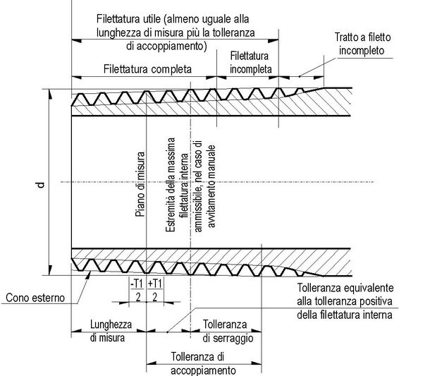
Fig. 3 : Terms referring to pipe threading
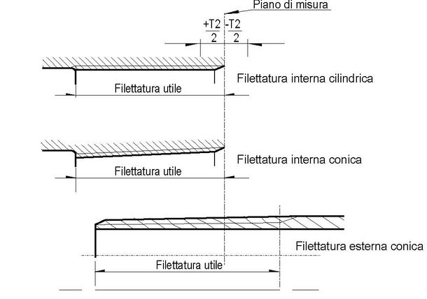
Fig 4: Position of the measuring plane, thread
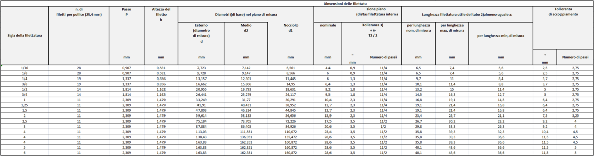
- the main dimensions have been converted into mm on the basis of 1 inch = 25.4 mm, starting from the number of threads per inch which determines the pitch P, from the formula h 0.640 327 P (Depth = Height of the thread) and from the nominal external diameter on the measuring plane.
The average thread diameter was then deduced by subtracting 1 time the h dimension from the external diameter and the core diameter by subtracting 2 times the h dimension from the external diameter.
The measuring length, tolerances and coupling tolerance were calculated directly
The other lengths in the table were obtained by subtracting or adding the tolerances or the coupling tolerance to the measuring length.
Tolerances and fit tolerances are expressed in mm and number of steps. - The arrangement of the internally threaded piece shall be such as to allow the external thread to be screwed in up to a minimum usable thread length given in column 16. Through internal threads may have a reduced usable thread length of not less than 80% of the values in column 17.
- For cylindrical thread fittings, calculate the diameter tolerances equivalent to those of columns 13 and 14 (1/16 of the length tolerances of column 13).